AND, OR, and NOT:


MF: lightly clean up to make the text more concise
Do we have any interest in salvaging the logic gates/XOR project that Selim and I worked on? --MF, 3/25/19
and, or, and not) and learn how they relate to electronic circuitry.In a circuit with billions of transistors, or even thousands of transistors, hardware designers can't think about each individual transistor. Just as programmers use abstraction, hardware architects use abstractions, in which a group of transistors and other circuit elements are considered as a single thing. What kinds of things? There are basically two kinds, one for memory and one for computation.
Memory is made out of flip-flops. A flip-flop is a circuit that has two stable states, on and off. An input signal can tell it to turn on, turn off, or change whatever it's state is. Once that happens, the flip-flop stays in the new state until it gets another signal. It has an output that reflects its state: on if the flip-flop is on, off if it's off.
The circuits to do computation are more interesting. They compute functions, just like reporters in Snap!. Since computers do a lot of arithmetic, you might think that the basic circuit functions would be addition, subtraction, multiplication, and division, but that's not the case. Of course there are circuits to do those things, but they're made out of logic gates: circuits that compute Boolean functions: and, or, and not.
The reason that Boolean functions are considered more fundamental is that their inputs and outputs can be represented with a single wire going into or out from the circuit. That's not true about arithmetic functions. If you consider a voltage on a wire as meaning 1, and no voltage as meaning 0, then you have to see that an adder will have three possible output values, because 1+1=2, which is neither 0 nor 1. By contrast, if you consider a voltage on a wire as meaning True, and no voltage as meaning False, then the output from a Boolean function of two inputs can still only be True or False, so only one output wire is needed.
You saw some examples in Unit 2 Lab 3: Making Decisions by Using Predicates: AND, OR, and NOT:


and.
This electric circuit shows a simplified way to emulate the Boolean operator and electronically. The two switches are in series; if both of the switches are on, the current flows and the light bulb turns on.
I wonder about making this simpler by including a pic of a battery in the animation. Students have a lot to manage in this endnote without this extra piece of information that isn't critical for the learning they are supposed to be doing. --MF, 12/4/17

| inputs | output | |
|---|---|---|
| A | B | A and B |
| False | False | False |
| False | True | False |
| True | False | False |
| True | True | True |
| inputs | output | |
|---|---|---|
| A | B | A and B |
| 0 | 0 | 0 |
| 0 | 1 | 0 |
| 1 | 0 | 0 |
| 1 | 1 | 1 |
or.
This electric circuit shows a simplified way to emulate the Boolean operator or electronically. The two switches are in parallel; if either (or both) of the switches are on, the current flows and the light bulb turns on.
As with the and tables, these two tables are identical except for whether they use true/false or ones/zeros.
In ordinary language, the word "or" can have two slightly different meanings. Inclusive or means "at least one of these": If it's raining or it's really cold out, you need your overcoat. (If it's both raining and cold, you'd still wear the coat.) Exclusive or means "this or that, but not both": Eat your vegetables or you won't get any dessert. (You'd feel cheated if you ate the vegetables and still didn't get dessert.) In computer science (as in mathematics) the word "or" by itself always means inclusive or, as you can see in this truth table. If you mean "exclusive or," you have to say that.
| inputs | output | |
|---|---|---|
| A | B | A or B |
| False | False | False |
| False | True | True |
| True | False | True |
| True | True | True |
| inputs | output | |
|---|---|---|
| A | B | A or B |
| 0 | 0 | 0 |
| 0 | 1 | 1 |
| 1 | 0 | 1 |
| 1 | 1 | 1 |
not.
This electric circuit shows a simplified way to emulate the Boolean operator not electronically. This switch is basically a circuit breaker: if the switch is on, the current flow is broken and the light bulb turns off; if the switch is off, the current flows directly to the light bulb and the light bulb turns on.
| input | output |
|---|---|
| A | not A |
| False | True |
| True | False |
| input | output |
|---|---|
| A | not A |
| 0 | 1 |
| 1 | 0 |
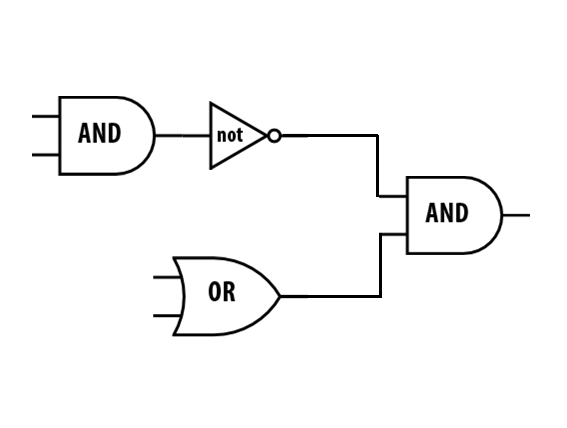
Inside a computer, Boolean operations are implemented in physical circuitry using logic gates. (A single gate implements one of the basic functions and, or, or not.) Logic circuits are often represented with drawings that help engineers see how the information will flow through a circuit. For example, the following diagram of a logic circuit with two gates represents the Boolean expression or((a)and(b))-booleans.png) . Can you see how?
. Can you see how?
or((a)and(b))-gate.png)
true?
true?


(true) and (false) report? What does not((true) and (false)) report? In expression II: What does (true) or (false) report? What does not((true) or (false)) report?not((true) and (false)) (on the right) report to the outermost and block?(true) and (false) (on the right) report to the outermost or block?true? (T stands for true, and F stands for false.)
|
|
|
How do engineers draw logic gates?
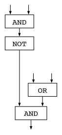 Engineers typically draw logic gates horizontally and use special shapes that represent each gate:


